As a supplier of U-Tube Heat Exchangers, I understand the critical role that optimizing the heat transfer area plays in enhancing the efficiency and performance of these essential industrial components. In this blog, I will delve into the various strategies and considerations for optimizing the heat transfer area of a U-Tube Heat Exchanger, drawing on my experience in the industry.
Understanding the Basics of U-Tube Heat Exchangers
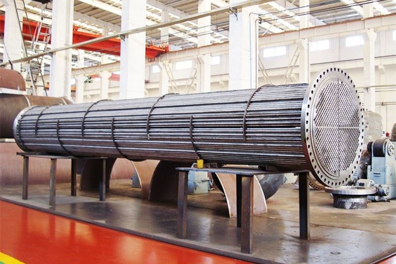
Before we explore the optimization techniques, it's important to have a clear understanding of how U-Tube Heat Exchangers work. These heat exchangers consist of a bundle of U-shaped tubes enclosed within a shell. One fluid flows through the tubes, while the other flows through the shell, allowing for heat transfer between the two fluids. The U-shaped design of the tubes allows for thermal expansion and contraction without causing excessive stress on the tubes or the shell.

The heat transfer area of a U-Tube Heat Exchanger is a key factor in determining its overall performance. A larger heat transfer area generally results in more efficient heat transfer, as it provides more surface area for the exchange of heat between the two fluids. However, increasing the heat transfer area also comes with certain challenges, such as increased cost, larger physical size, and potential pressure drop issues.
Strategies for Optimizing the Heat Transfer Area
1. Tube Diameter and Length
The diameter and length of the tubes in a U-Tube Heat Exchanger have a significant impact on the heat transfer area. Smaller tube diameters generally result in a larger heat transfer area per unit volume, as they provide more surface area for heat transfer. However, smaller tubes also increase the pressure drop across the tubes, which can require more pumping power. Therefore, it's important to find the right balance between tube diameter and pressure drop.
Increasing the length of the tubes can also increase the heat transfer area. However, longer tubes can lead to higher pressure drops and may require more space for installation. When selecting the tube length, it's important to consider the available space, the pressure drop limitations, and the overall heat transfer requirements.
2. Tube Layout and Pitch
The layout and pitch of the tubes in a U-Tube Heat Exchanger can also affect the heat transfer area. A triangular tube layout generally provides a higher heat transfer area per unit volume compared to a square tube layout. This is because the triangular layout allows for a closer packing of the tubes, resulting in more surface area for heat transfer.
The tube pitch, which is the distance between the centers of adjacent tubes, also plays a role in determining the heat transfer area. A smaller tube pitch can increase the heat transfer area, but it can also increase the pressure drop and make the cleaning and maintenance of the heat exchanger more difficult. Therefore, it's important to select the tube pitch based on the specific requirements of the application.
3. Tube Material and Surface Finish
The material and surface finish of the tubes can have a significant impact on the heat transfer performance of a U-Tube Heat Exchanger. Materials with high thermal conductivity, such as copper and aluminum, can enhance the heat transfer rate. Additionally, a smooth surface finish can reduce the fouling of the tubes, which can improve the heat transfer efficiency over time.
However, the choice of tube material also needs to consider factors such as corrosion resistance, mechanical strength, and cost. For example, in applications where the fluids are corrosive, stainless steel or other corrosion-resistant materials may be required.
4. Shell Design
The design of the shell in a U-Tube Heat Exchanger can also affect the heat transfer area and performance. A well-designed shell can ensure proper distribution of the shell-side fluid across the tube bundle, which can enhance the heat transfer efficiency. Additionally, the use of baffles in the shell can increase the turbulence of the shell-side fluid, which can further improve the heat transfer rate.
However, the design of the shell also needs to consider factors such as pressure drop, manufacturing cost, and ease of maintenance. For example, a more complex shell design with multiple baffles may increase the pressure drop and the manufacturing cost, but it may also provide better heat transfer performance.
Considerations for Optimizing the Heat Transfer Area
1. Thermal Efficiency vs. Pressure Drop
When optimizing the heat transfer area of a U-Tube Heat Exchanger, it's important to balance the thermal efficiency with the pressure drop. Increasing the heat transfer area generally improves the thermal efficiency, but it also increases the pressure drop across the heat exchanger. A higher pressure drop requires more pumping power, which can increase the operating cost. Therefore, it's important to find the optimal balance between thermal efficiency and pressure drop based on the specific requirements of the application.
2. Fouling and Maintenance
Fouling of the tubes and the shell can significantly reduce the heat transfer efficiency of a U-Tube Heat Exchanger over time. Therefore, it's important to consider the potential for fouling when optimizing the heat transfer area. For example, selecting a tube material and surface finish that are resistant to fouling can help to maintain the heat transfer efficiency. Additionally, designing the heat exchanger for easy cleaning and maintenance can also help to reduce the impact of fouling.
3. Cost and Space Constraints
Optimizing the heat transfer area of a U-Tube Heat Exchanger also needs to consider the cost and space constraints. Increasing the heat transfer area generally requires more materials and a larger physical size, which can increase the cost and the space requirements. Therefore, it's important to find the most cost-effective solution that meets the heat transfer requirements while also fitting within the available space.
Related Products and Their Role in Heat Transfer Systems
In addition to U-Tube Heat Exchangers, there are other products that play important roles in heat transfer systems. For example, Scrubber Tower can be used to remove contaminants from the fluids before they enter the heat exchanger, which can help to reduce fouling and improve the heat transfer efficiency. Drying Tower can be used to remove moisture from the fluids, which can also have a positive impact on the heat transfer performance. And Fixed Tube Sheet Heat Exchanger is another type of heat exchanger that can be used in combination with U-Tube Heat Exchangers to meet different heat transfer requirements.
Conclusion
Optimizing the heat transfer area of a U-Tube Heat Exchanger is a complex process that requires careful consideration of various factors, including tube diameter and length, tube layout and pitch, tube material and surface finish, shell design, thermal efficiency vs. pressure drop, fouling and maintenance, and cost and space constraints. By understanding these factors and implementing the appropriate optimization strategies, we can enhance the efficiency and performance of U-Tube Heat Exchangers, which can ultimately lead to cost savings and improved productivity for our customers.
If you are interested in learning more about our U-Tube Heat Exchangers or other related products, or if you have specific heat transfer requirements that you would like to discuss, please feel free to contact us. We are committed to providing high-quality products and solutions that meet the needs of our customers.
References
- Incropera, F. P., DeWitt, D. P., Bergman, T. L., & Lavine, A. S. (2019). Fundamentals of Heat and Mass Transfer. John Wiley & Sons.
- Shah, R. K., & Sekulic, D. P. (2003). Fundamentals of Heat Exchanger Design. John Wiley & Sons.
- Kakac, S., & Liu, H. (2002). Heat Exchangers: Selection, Rating, and Thermal Design. CRC Press.


